
Da Vinci bridge calculations stand out as some of history’s most elegant solutions to challenging structural engineering problems.
These mathematical principles behind Leonardo’s self-supporting design still guide engineers today, especially when they’re working on earthquake-resistant structures, portable military bridges, or sustainable projects that rely on compression forces instead of expensive materials or permanent fasteners.
MIT studies confirmed the structural soundness of his 500-year-old equations. Norway even built a pedestrian bridge using these same ideas, demonstrating that da Vinci’s approach to load distribution and geometric stability remains adequate for modern infrastructure needs.
Architects and engineers continue to rely on Leonardo’s compression-only calculations for structures that require seismic resilience, support heavy loads without the use of fasteners, or rapid deployment.
His grasp of how interlocking members share weight through geometry has inspired emergency bridges and modular construction systems alike.
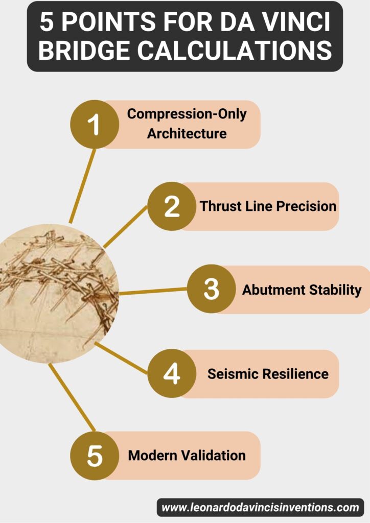
How Da Vinci Bridge Calculations Define Structural Integrity Through Compression-Only Architecture
Da Vinci bridge calculations demonstrate how compression-only structures achieve stability by carefully positioning the thrust line and utilizing friction lock mechanisms.
The design avoids tensile stresses and stays structurally feasible through mathematical relationships that govern arch geometry and load distribution.
Understanding the Compression-Only Arch and Thrust Line Within Masonry Depth
The compression-only arch sits at the heart of da Vinci’s method. Engineers must keep the thrust line within the masonry depth to prevent tensile failures. That takes careful calculation of the arch’s curvature and loading.
Modern analysis shows Leonardo understood thrust-line theory instinctively. The Golden Horn bridge design uses geometric ideas that wouldn’t become mainstream for centuries.
Key thrust line requirements:
- Stays within the middle third of the arch depth
- Doesn’t exceed masonry compression limits
- Needs a continuous load path from the crown to the abutments
The flattened parabolic arch brings its own set of challenges. Engineers use trigonometric layout methods—basically echoing da Vinci’s sketches—to calculate thrust line deviation.
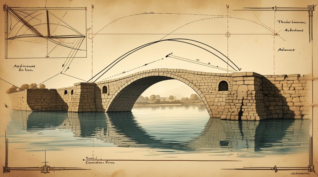
Calculating Lateral Thrust and Abutment Stability for Single-Span Masonry Arch Designs
Lateral thrust calculations show the horizontal forces sent to the bridge abutments. With a single-span masonry arch, these forces concentrate at two main points. Engineers figure out thrust magnitude from the arch’s geometry and loading.
Abutment stability calls for massive foundations to resist overturning moments. The span-to-rise ratio matters—a flatter arch pushes out more horizontal force.
Critical stability factors:
- Foundation bearing capacity on actual soils
- Abutment massing for thrust resistance
- Safety factor against sliding and overturning
Modern feasibility studies look at 16th-century methods. Stone ashlar blocks require precise cutting to achieve the parabolic profile without the use of centering falsework.
Bearing Capacity and Foundation Settlement Testing in 16th-Century Construction Feasibility
Foundation settlement testing highlights key constraints for building the bridge. Engineers analyze bearing capacity using techniques available in 1502. The massive abutments need deep foundations to transfer loads safely.
Settlement tolerance calculations indicate the acceptable range of differential movement between supports. Modern studies use dimensional similitude to test foundations at smaller scales.
Foundation requirements include:
- Pile foundations reaching bedrock
- Raft foundations to spread out loads
- Settlement monitoring during construction
A 240-meter span creates huge foundation loads for the 16th century. Bearing capacity analysis helps determine if old construction methods could handle the job.
Keystone Action and Friction Lock Mechanisms in Self-Supporting Bridge Design
Keystone action spreads loads through the arch crown, while friction lock mechanisms keep the structure together. The self-supporting design eliminates the need for mechanical fasteners by relying on the geometric interlocking of pieces.
Each stone block relies on friction and interlock, rather than mortar joints. This needs precise piece length optimization for equilibrium. The self-supporting bridge concept shows advanced force transfer ideas.
Friction lock principles:
- Adjacent blocks interlock mechanically
- Compression forces trigger frictional resistance
- No tensile connections needed for stability
Modern replicas using glulam wood confirm these friction mechanisms. Engineers test 3D-printed models to verify whether geometry alone can transfer loads.
Load Paths and Stress Concentration Analysis for Flattened Parabolic Arch Geometry
Load paths in the flattened parabolic arch lead to complex stress patterns. Engineers examine stress concentration where the geometry changes. The arch rib carries the main loads, while the spandrel areas handle secondary forces.
Dynamic response calculations cover wind stability and seismic resilience. Compression-only structures offer redundancy through several load transfer paths.
Critical analysis points:
- Max stress at quarter-span points
- Load spread through arch depth
- Stability under live loads and environmental forces
Modern structural analysis confirms the design’s feasibility with computational tools Leonardo never had. The math behind arch behavior backs up his intuitive engineering.
Why Modern Engineering Still Relies on Da Vinci Bridge Calculations for Seismic Resilience
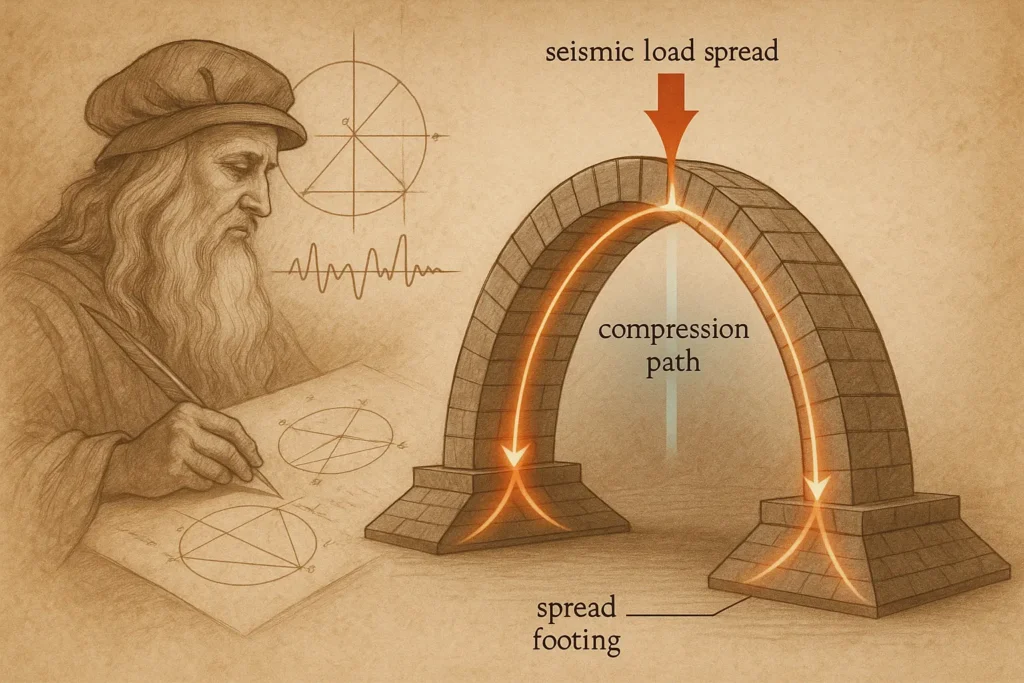
Da Vinci bridge calculations provide key insights for earthquake-resistant design, utilizing compression-only structures and spread footings that effectively distribute seismic forces. The Leonardo da Vinci Golden Horn Bridge exemplifies structural principles that engineers continue to use in addressing seismic challenges.
Seismic Stability and Dynamic Response in Compression-Only Structures
Compression-only arch structures handle earthquake forces with geometric stability, in addition to material strength. The thrust line remains within the masonry depth during earthquakes, preventing tensile failures that can damage regular bridges.
Engineers study da Vinci’s flattened arch to see how compression forces move during ground motion. The parabolic shape channels lateral thrust to spread foundations, dodging stress points that often fail first in quakes.
Modern seismic codes use these ideas for unreinforced masonry. Compression-only systems offer redundancy that steel and concrete bridges often lack.
Abutment Massing and Overturning Resistance Through Splayed Foundation Design
Leonardo’s abutment stability calculations explain how massive foundations stop overturning in earthquakes. The splayed foundation boosts bearing capacity and lowers the center of gravity.
Today’s engineers use similar abutment massing for seismic zones. The foundation shape spreads loads over a larger area of soil, reducing settlement risks. This is especially useful for bridges on soft soils that are prone to liquefaction.
Key Foundation Principles:
- Wider width-to-height ratios
- Lower center of gravity
- Better soil bearing spread
- Less overturning moment
Settlement Tolerance and Factor of Safety in Leonardo da Vinci Golden Horn Bridge Analysis
The MIT study found impressive settlement tolerance in da Vinci’s design. Engineers tested the foundation’s movement by separating the support platforms until the bridge finally collapsed.
Modern bridge codes use these settlement ideas with higher safety factors. The compression-only structure adapts to uneven settlement through its geometry, rather than material failure.
Load paths shift automatically when foundations settle unevenly. This self-adjusting behavior gives seismic resilience that rigid structures can’t match.
3D-Printed Scale Model Testing and Dimensional Similitude at 1:500 Scale
Researchers built 3D-printed blocks at a 1:500 scale to check da Vinci’s structural math. The 126-block model showed how scaling laws affect compression arch behavior under seismic loading.
Dimensional similitude testing reveals how proportions impact seismic performance. Engineers use these scaling rules for modern compression arches in earthquake zones.
The friction lock between blocks creates distributed stiffness; no mortar is needed. This allows the bridge to flex during earthquakes while maintaining its integrity.
Wind Stability and Load Distribution Under Live Loads Using Period Methods
Da Vinci’s construction methods addressed wind stability through geometric proportions and intelligent load distribution. The span-to-rise ratio naturally resists wind without extra bracing.
Modern engineers look at these old methods to trace load paths in compression structures. Wind forces move through the arch rib and spandrel fill, not just at connection points.
Load Distribution Features:
- Keystone action spreads wind loads sideways
- Spandrel fill adds mass damping
- Arch rib geometry channels forces to the foundations
- Deck-arch interaction creates composite behavior
The self-supporting design skips fatigue-prone connections that usually fail under repeated wind loads.
How Da Vinci Bridge Calculations Inspire Contemporary Construction From Norway’s Glulam Arch to Modular Systems
Da Vinci bridge calculations highlight compression-only arch principles that modern engineers use with glulam construction, 3D-printed scale models, and modular systems. These calculations guide everything from piece length optimization to foundation settlement testing in current bridge design.
Glulam Parabolic Arch Design and Steel-Reinforced Deck in Norway: Replica Applications
The Norway bridge project from 2001 brings Leonardo’s thrust line calculations to life in a glulam parabolic arch. Engineers used laminated wood beams for the flattened arch, sticking to the original compression-only principles.
The steel-reinforced deck spreads live loads across the arch rib. This deck-arch interaction gives redundancy, much like Leonardo’s stone block distribution would have done.
Key specifications:
- Main span: 40 meters
- Total length: 109 meters
- Material: Glulam timber with steel reinforcement
- Construction cost: 12 million Norwegian kroner
Modern glulam lets engineers fine-tune the span-to-rise ratio. They can calculate the exact thrust line position within the wood depth, ensuring the bridge remains stable under dynamic loads.
Friction and Interlock Principles in 3D-Printed Blocks for Modern Testing
MIT’s groundbreaking validation study used 3D-printed blocks to test Leonardo’s friction lock calculations.
The 1:500 scale model had 126 individual pieces. These relied entirely on friction and interlock mechanisms.
The 3D-printed model demonstrated that mortar versus dry joints calculations remain valid after 500 years. Each block transfers loads through direct contact, without the use of adhesives or fasteners.
Testing parameters:
- Scale ratio: 1:500
- Block count: 126 pieces
- Assembly time: 6 hours printing
- Load capacity: Verified under foundation movement
Dimensional similitude laws show that Leonardo’s contact calculations scale accurately. The friction lock and interlocking wood design principles remain effective with modern materials and methods.
Piece Length Optimization and Trigonometric Layout for Self-Supporting Wood Variants
Leonardo’s trigonometric layout calculations help determine the best beam lengths for structural efficiency.
Modern engineers utilize these optimization formulas to design self-supporting bridge variants using standard lumber.
The geometric relationships between beam angles and contact points follow strict math rules. Each piece must hit specific load paths to maintain steady keystone action throughout the bridge.
Builders today often use 2×6 lumber or larger timbers, adhering closely to Leonardo’s original proportions. The trigonometric layout maintains a solid bearing capacity at every connection.
Critical measurements:
- Beam angle calculations
- Contact surface optimization
- Load transfer points
- Assembly sequence planning
Deck-Arch Interaction and Spandrel Fill Considerations in Modern Analogs
Modern modular bridge systems use Leonardo’s spandrel fill calculations to optimize load distribution. The deck-arch interaction creates composite behavior, which increases stiffness and seismic resilience.
Bailey-style military bridges employ similar concepts for rapid setup. These systems depend on calculated load paths that distribute weight through compression members.
Engineers need to consider how deck and arch components settle differently. Spandrel areas give important lateral stability under wind and dynamic loads.
Leonardo’s no-centering construction approach cuts out the need for temporary falsework. That reduces project costs and construction headaches.
Modern applications include emergency bridge builds, where centering is just not practical. The Golden Horn bridge design required 43 meters of ship clearance, a standard still used for navigational channels.
Contemporary bridge designers use these clearance numbers for commercial shipping needs. Foundation settlement testing backs up Leonardo’s abutment stability calculations, even without centering support.
The structure reaches its full load capacity immediately after keystone placement, ensuring navigational access is available right away.
Frequently Asked Questions
Engineers and students often have questions about da Vinci bridge calculations and load-bearing formulas. These calculations help determine structural capacity, efficiency ratings, and safety factors for bridge designs.
How do you calculate how much a bridge can hold?
Bridge load capacity calculations figure out the maximum weight a structure can safely support. Engineers look at the materials, dimensions, and design of each bridge component.
The basic formula uses the bridge’s cross-sectional area, material strength, and safety factors. For da Vinci’s self-supporting bridge, calculations focus on compression forces rather than tension.
Engineers multiply the material’s compressive strength by the effective cross-sectional area. Then they add a safety factor—usually between 2 and 4—to make sure the bridge won’t fail if overloaded.
Load distribution patterns also affect capacity. Da Vinci’s bridge design utilizes interlocking beams to distribute weight evenly across the entire structure.
What is the Davinci method of bridge?
The Da Vinci bridge method uses interlocking wooden beams that support each other through compression. No fasteners, nails, or mortar hold the pieces together.
Each beam locks into place with the others using precise angles and weight distribution. The structure remains intact thanks to the friction between its parts.
This creates a self-supporting bridge that depends entirely on compression. The interlocking mechanism spreads loads across all the members.
Military engineers preferred this method because it enabled quick construction without the need for specialized tools. Soldiers could make crossings with local timber and basic carpentry skills.
What is the bridge formula?
The bridge formula calculates the maximum weight allowed on vehicle axles based on axle spacing. Federal regulations use this to protect bridges from overloading.
The formula: W = 500 × (LN/(N-1) + 12N + 36). W is max weight in pounds, L is axle spacing in feet, N is the number of axles.
This helps figure out safe vehicle weights for existing bridges. It prevents damage from trucks that go over design load limits.
For structural analysis, engineers use different formulas for different bridge types. Beam bridges utilize moment and shear calculations, while arch bridges focus on compression.
What is the formula for calculating bridge efficiency?
Bridge efficiency is the ratio of functional load capacity to total structural weight. The formula: Efficiency = (Live Load Capacity ÷ Dead Load) × 100%.
Higher efficiency ratios mean better design. Most modern bridges have a coefficient of friction between 0.3 and 0.8, depending on the span and materials used.
Da Vinci’s bridge achieves high efficiency due to its self-supporting geometry. The design eliminates unnecessary material while maintaining strength through compression.
Material use affects efficiency a lot. Bridges that use less material but hold more weight score higher.
What is the formula for load calculation?
Total load refers to the sum of dead loads and live loads acting on the bridge. The formula: Total Load = Dead Load + Live Load + Environmental Loads.
Dead loads are the bridge’s own weight and permanent fixtures. Live loads include traffic, pedestrians, and any temporary loads.
Environmental loads cover wind, snow, and seismic forces. Engineers add these up using combination factors from building codes.
For Da Vinci bridges, compression-only analysis simplifies load calculations. The entire structure transfers loads through compression, rather than complicated bending moments.
Is 10 or 20 psf dead load?
Dead load values depend significantly on the materials used and the construction method employed in building the bridge. You’ll usually see dead loads anywhere from 10 to 150 pounds per square foot (psf).
If you’re working with lightweight timber, consider using 10-15 psf. Concrete bridge decks? Those usually call for 50-75 psf in your calculations.
Steel beam bridges typically fall within the 20-40 psf range, although this depends on the size of the members. Material density and the thickness of everything will affect that number.
Engineers figure out dead loads by multiplying the density of the material by its thickness. Wood weighs approximately 35-50 pounds per cubic foot, while concrete weighs about 150 pounds per cubic foot.
 Leonardo Bianchi is the founder of Leonardo da Vinci Inventions & Experiences, a travel and research guide exploring where to experience Leonardo’s art, engineering, and legacy across Italy and Paris.